JK1SXR
=>Japanese
Return to "A. Home"
1. From yagi to
quad antennas
2. Quad antenna
modification 1
3. Quad antenna
modification 2
4. Combined quad
dimensions
Return to "A. Home"
1. From yagi to
quad antennas
2. Quad antenna
modification 1
3. Quad antenna
modification 2
4. Combined quad
dimensions
B2. V/U antennas for low earth orbit satellites
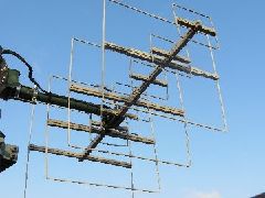
2. LEO sat ant. modification 2 / from 3-element to 4-element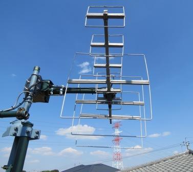 As described earlier, the current LEO sat antenna configulation settled down to 145 MHz / 3 elements and 435 MHz / 6 elements after a sereis of trials based on the assumption that the elevation angle was fixed.
Since the elevation angle control has been newly employed, a narrower antenna pattern shall be no more major problem. Thus I decided to modify the 3-element 144 MHz antenna back to the original 4-element type.
The following is a summary of the modification works.
1) The second director, D2
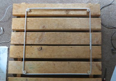
The exisiting design consisted of the 3 elements of reflector, radiator and director. Thus the work here is to make the 2nd director, D2.
The D2 element length was set to 1880 mm as in the material mentioned before. An aluminum pipe of outer diameter of 6 mm was employed in the same manner as for the other 3 elements.
It requires a certain technique to bend the 6-mm dia. pipe and to complete the required dimensions.
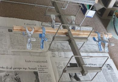
My way is to set up a simple 4-corner arrangement with pieces of a wooden bar of outer diamenter of 20 mm as in the picture. The pipe is bent along the 4 corners.
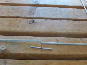
A piece of 4-mm aluminum tubing is used to join the two ends of the D2 frame. As the surface of aluminum tubing on the market is normally anodized and non-conductive, the anodised suface shall be stripped away by using a file.
This 4-mm diameter piece is inserted into the ends of the 6-mm tubing, and they are swaged for a stable connection.
2) D2 struts
The boom and struts of my LEO sat antenna consit of wood. The D2 strut was made in the same manner.
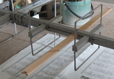
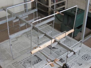
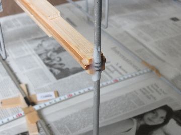
First, a wood plate of about 600 mm long, 20 mm wide and 5 mm thick, is inserted into the main boom at the required position .
(As the main boom consists of 2 parallel pieces of wood plate, the strut can be inserted in between the parallel booms. See the pictures.)
At both ends of the strut, a holding section which accomodates the 6-mm pipe shall be arranged.
First the 6-mm diameter holes are drilled at the required positions on both ends of the strut. The required length can be oobtained by cutting off both ends so that a half of the 6-mm hole remains.
A piece of wood plate of 5-mm thickness does not give a sufficient strength. Therefore another 2 peices of 5-mm plate shall be applied to strengthen the strut at both right and left sides.
Furhter at the center sides, another 2 sets of 5-mm thick plate are added at both right and left sides.
All shall be glued together by applying wood adhesive.
With these works, the strut thickness becomes 25 mm, same as that of the main boom.
3) Director D2 fixing
Two component adhesive of epoxy type is applied to the two places at the middle section of the D2 frame, and also to both ends of the strut. Then the D2 frame is put into the position.
This brings about the sturdy fixing to withstand ordinary typhoons and spring gales.
4) Completion
 Finally paint is applied to the D2 frame and the strut for protection.
Though the modification to the 4-element is not anything which dramatically improves the performance, a certain level of effect has been obtained.
Copyright © 2013 JK1SXR/abemasa. All Rights reserved.